Simulation
How bulk material flows through transfer chutes, onto conveyors and into ships
This section covers simulation work exploring how bulk material moves through transfer chutes, conveyor systems and ship-loading equipment. The method is DEM—the discrete element method—which models the material particle by particle to see where flow slows, where it builds up, and what changes when you alter the geometry.
Below you'll find case studies with video, guides explaining how DEM works, and answers to common questions. We work with companies in Australia and across Asia.
Simulation Videos
Before-and-after flow simulations: the current design next to a proposed change, under the same conditions.
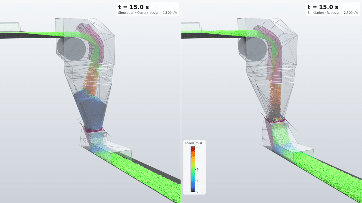
Transfer chute flow simulation: current and proposed design
A DEM simulation of material falling through a transfer chute onto a belt conveyor. The current chute is on the left and a proposed design on the right; particles are coloured by speed, from blue (slow) to red (fast). In the current design, material slows and crowds at the bottom of the chute where it meets the belt. In the proposed design it leaves the chute travelling with the belt.
Guides & Articles
Plain-English explanations of chute flow analysis and DEM simulation.
The Discrete Element Method (DEM) Explained
How DEM simulation models bulk materials particle by particle, what it is good for, and where its limits are.
Transfer Chute Flow Analysis: A Plain-English Guide
What transfer chute flow analysis is, how simulation shows blockages and wear before steel is cut, and the data that makes the results reliable.
Frequently Asked Questions
Want to Talk About What You're Seeing?
If you've got a chute that keeps blocking, a belt that loads off-centre, or a throughput number that doesn't add up, we're happy to talk through what you're seeing and whether simulation would tell you something useful.
Get in touch